Once I get settled in to life at MIT, I hope to start up another fusor project as soon as time permits. I will continue to keep a log of its progress on this blog. In the meantime...here are some photos (and a video!) compiled from the life of Fusor Mark I:
Friday, September 3, 2010
No Sleep 'Till Fusion
Another school year is starting, and I find myself on the East Coast, waiting to start taking grad classes in a week. Unfortunately, we did not detect any neutrons coming out of the Fusor Mark I this summer, and I have sadly been forced to put my quest for fusion on hold, at least for now. The good news is that Fusor Mark I is still in working order back at LMU, and I hope that some bright student (or students) will be able to carry on the fusor work that I left behind. I have mentioned them before, but I would like to again thank Anatol Hoemke and Dr. John Bulman again for all of their help and support in this project. Without you guys this never would have been possible.
Once I get settled in to life at MIT, I hope to start up another fusor project as soon as time permits. I will continue to keep a log of its progress on this blog. In the meantime...here are some photos (and a video!) compiled from the life of Fusor Mark I:


Once I get settled in to life at MIT, I hope to start up another fusor project as soon as time permits. I will continue to keep a log of its progress on this blog. In the meantime...here are some photos (and a video!) compiled from the life of Fusor Mark I:
Tuesday, June 1, 2010
Searching for Neutrons...
We have been up and running for about a week now, but unfortunately all manner of voltage, pressure, and time combinations have yet to show any evidence of neutron production. Because we were getting weird voltage readings when the system was attached to the power supply, we decided to re-design the electrical feedthrough and take the chamber apart to clean it. We were expecting a bit of deposition on the inside but were unprepared for the amazing amount of color on the inside. Note the spots where the plasma "jets" impacted the side of the reactor chamber. Also, the tinning on the grid had completely been etched away (and deposited on the chamber wall), leaving bare copper on the grid.

Thursday, May 13, 2010
Some Cool Plasma
In order to check out the gas handling system, Anatol and I ran the system using just atmosphere. We made sure that it was possible to attain a balance between inflow (from the bottle/atmosphere) and outflow (through the pump) at whatever pressures we wanted. As the system was fully put together at this point, we played around with some atmospheric plasmas.
The first plasma is at high vacuum ( < 20 mTorr) at about 10 kV. The jet coming off the upper left stabilized and became more "focused" the longer the plasma was maintained.

The second plasma is at the same voltage but at a much lower vacuum (around 1 Torr). At this pressure, the plasma only existed right around the grid, making the grid itself appear to glow.
The first plasma is at high vacuum ( < 20 mTorr) at about 10 kV. The jet coming off the upper left stabilized and became more "focused" the longer the plasma was maintained.
The second plasma is at the same voltage but at a much lower vacuum (around 1 Torr). At this pressure, the plasma only existed right around the grid, making the grid itself appear to glow.
Deuterium System
In the previous post, I mentioned a deuterium handling system, and figured that it was worthy of its own post. The system consists of:
1.) A 20 liter lecture bottle of deuterium and a regulator.

2.) A fine control needle valve and line bleedoff:

3.) And a Teflon-shielded inlet to the chamber itself (we wanted to make sure that the copper line was completely insulated from the floating voltage on the chamber).
1.) A 20 liter lecture bottle of deuterium and a regulator.
2.) A fine control needle valve and line bleedoff:
3.) And a Teflon-shielded inlet to the chamber itself (we wanted to make sure that the copper line was completely insulated from the floating voltage on the chamber).
New Developments!
Wow, the end of the school year definitely caught up with me, but now finals are over, and I can devote more time to fusion. Here is what has taken place since the last post:
1.) Anatol machined a Teflon standoff (the white piece) to go between the chamber and the vacuum hose. We installed it, and it was effective in stopping all plasma discharge down the hose.

2.) The old grid (the one that was soldered together) finally couldn't take the heat anymore, and the solder vaporized, ruining the grid. After tediously scraping the bits of solder from the inside of the chamber, we decided that all future grids needed to be either spot welded or made out of one continuous piece of wire.

3.) We found a box of TC probes in the lab, and attached a T joint to the end of the chamber to accommodate the probe. (see picture 1) Now we can measure the pressure in the chamber without using Dr. Bulman's chamber in series with ours! With this new setup, we were able to max out our 1 mTorr gauge (i.e. pressure below 1 mTorr) and the chamber only takes minutes instead of days to pump down.
4.) We found out that the positive "ground" from the power supply is not the same as earth ground, and actually floats above earth ground by about 1200 volts when the system is at maximum power.
5.) Fabricated a new grid 1 3/4'' in diameter with a continuous piece of wire.
6.) Fixed up the deuterium gas handling system (see next post) and bought 3 BTI bubble detectors.
1.) Anatol machined a Teflon standoff (the white piece) to go between the chamber and the vacuum hose. We installed it, and it was effective in stopping all plasma discharge down the hose.

2.) The old grid (the one that was soldered together) finally couldn't take the heat anymore, and the solder vaporized, ruining the grid. After tediously scraping the bits of solder from the inside of the chamber, we decided that all future grids needed to be either spot welded or made out of one continuous piece of wire.
3.) We found a box of TC probes in the lab, and attached a T joint to the end of the chamber to accommodate the probe. (see picture 1) Now we can measure the pressure in the chamber without using Dr. Bulman's chamber in series with ours! With this new setup, we were able to max out our 1 mTorr gauge (i.e. pressure below 1 mTorr) and the chamber only takes minutes instead of days to pump down.
4.) We found out that the positive "ground" from the power supply is not the same as earth ground, and actually floats above earth ground by about 1200 volts when the system is at maximum power.
5.) Fabricated a new grid 1 3/4'' in diameter with a continuous piece of wire.
6.) Fixed up the deuterium gas handling system (see next post) and bought 3 BTI bubble detectors.
Friday, February 26, 2010
Low Vacuum Plasma
Interesting Effects...
This video is a clip from a very low vacuum run (around 200 microns). Notice how the plasma is not diffused throughout the chamber but forms a "halo" around the wires of the grid.
It Works!
As you can hear in the video, the plasma starts to appear when the variac is at 20 volts (corresponding to roughly -1500V from the power supply). From what I have read so far, the shape of the plasma is due in part to the geometry of the inner grid, and the jet, or "bugle" coming out of the left side has to do with how the grid is shaped.
While this plasma looks really cool, this test was just the first in a series of steps to achieving nuclear fusion. This test run was just done on atmospheric gas, which is much too heavy to fuse with the voltages that I am running at. However, the next step is to build an inlet to let deuterium gas into the chamber, which should fuse when the reactor is turned on.
Wednesday, February 24, 2010
2 More Days Until the First Test Run!

The first test of the chamber will not actually produce fusion reactions, but should ionize the atmospheric gas that is left in the chamber. If we can manage to ionize this gas, then the fusor proof-of-concept is good and we can proceed to add a gas inlet to the chamber to let deuterium in.
Power Supply

Inner Grid and Feedthrough


Sunday, February 14, 2010
Vacuum Test 3
In addition to making sure that the system could still hold a vacuum after the feedthrough had been attached, we found another (newer) vacuum gauge that fit the plug for the sensor in Dr. Bulman's chamber, and compared the readings of both gauges.
It appears that the third test was a success, as no audible leaks were detected when the pump was first turned on, and the chamber got down to a pressure of about 200 microns on the old gauge. However, when we swapped the old gauge for the new one, we recorded a pressure of 34 microns! As we have no way of calibrating the gauges at this time, it is impossible to decisively say which gauge is the "correct" one, or even if either of the gauges are correct. However, at this point, Anatol and I agreed that the newer gauge was probably more accurate just on the account of it being new, so we will use that one for the time being.
Tuesday, February 9, 2010
Vacuum Setup

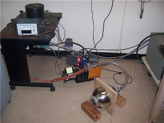
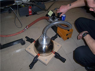
Here is a picture of the vacuum setup that was described in the post for the first vacuum test (although this picture is of the second test). My chamber is the one on the ground, and is connected to the orange and black roughing pump by the clear line. Dr. Bulman's chamber is the black cylinder on the back of the table, and the pressure gauge is in front of it. The gauge is connected to a thermocouple sensor which is mounted inside of the chamber. In the future, I hope to buy a thermocouple sensor and build a feedthrough directly into my fusor, as the roughing pump has to work twice as hard in this configuration to pump out both chambers.
Vacuum Test 2
View Through the Viewport
Lathe
Viewport Design

Thursday, February 4, 2010
A Short Introduction to Pressure Terminology
The units of pressure were a bit confusing to me before I started this project, so to clarify things for the reader in advance, here is a quick tutorial about pressure and its units.
In order for the fusor to produce fusion reactions, the inside of the chamber must be at a very low pressure, or put another way, at a very high vacuum. Out in space, there is an almost perfect vacuum. On the earth, the atmosphere is filled with gas, which exerts pressure on everything. You are used to this pressure and do not notice it in your everyday life, but if you drive up a mountain or fly on an airplane, your ears will pop, as the atmosphere is thinning and the pressure is dropping.
The standard pressure at sea level is defined as 1 atm (atmosphere), which is roughly 15 pounds per square inch. The pressure of the earth's atmosphere at sea level will apply a force of 15 lbs on every square inch exposed to the atmosphere. Easy, right? Well, here is where things start to get confusing.
There are many different systems of measuring pressure. The SI unit of pressure is the pascal (Pa), but I have not encountered this notation very often in my online fusor research. More common is the Torr, which is roughly the fluid pressure exerted by a millimeter of mercury. One atm is equal to 760 Torr. However, vacuum pressure is much, much less than atmospheric pressure, so normally only a tiny fraction of a Torr is measured. For example, light bulbs are normally evacuated to 0.1 to 0.01 Torr. The vacuum pressure on the moon is roughly 10^-11 Torr.
From my online research so far, it seems that a vacuum of about 20-60 mTorr (m stands for 10^-3) is needed. Because one Torr is roughly equivalent to a millimeter of mercury, another symbol for a Torr is mmHg. Thus, one mTorr will be equal to one micrometer (10^-6 meters) of Hg, and so the term "micron" is interchangeable with "mTorr." Whew! Long story short, my fusor will need to obtain pressures of about a tenth of the vacuum pressure in a light bulb in order to operate.
There are many other measurements of pressure, and if you are really interested, wikipedia has good articles on pressure (http://en.wikipedia.org/wiki/Pressure) and vacuum (http://en.wikipedia.org/wiki/Vacuum) that I obtained most of the information above from. Hope this helps!
First Vacuum Test


When we turned the pump on for the first time, Dr. Bulman said it sounded fine so there weren't any large leaks. It made a constant gurgling sound and didn't sputter. We left the pump running for a few days, and the pressure went down to 60 microns or so, but then increased to 200 microns and stayed there. Anatol then closed off the valve (as seen in the top picture) and the system did not drop pressure immediately, which was a good sign. It took about a day for the pressure to rise close to standard atmospheric pressure.
The first test was a success! Not only did we manage to get the pressure down to a very low level, but when the pump was turned off, the chamber was able to hold the vacuum for a while. Also, when we disassembled the chamber later, the gasket was still in good condition.
Vacuum Container: First Stage

Here, both bowls are fit together, without the particle-board jig. We used vacuum grease around the gasket to prevent any small leaks into the container.
Monday, January 25, 2010
Schematic: Custum Vacuum Fitting
Progress Report 1: Vacuum Chamber

The first part of the fusor construction has dealt with creating a vacuum chamber. In order for the fusion reactions to work, a reasonably high vacuum is needed (on the order of 20 to 40 microns). In order to get this vacuum, two things are needed: a good pump (or system of pumps) and a chamber that is vacuum-tight. I managed to scavenge an Alcatel roughing pump, which I will use for the proof-of-concept fusor. For the second iteration, I will incorporate a turbomolecular pump that one of the professors was kind enough to loan me.
As for the chamber, I bought two large, stainless steel mixing bowls with flat flanges to be the main body. The first order of business was making a connector so that the chamber could be attached to the pump. In order to do this, the lab manager and I machined a cylinder of aluminum so that one side could be J-B welded (epoxied) to one of the bowls and the other side would be a connecting flange to the pump hose attachment.
Basic Overview of Fusion
The most common question that I get when I tell people I am trying to build a nuclear reactor is, "Gee isn't that dangerous?!? What if it blows up?" Well, yeah, it is kind of dangerous, but this reactor will never explode, much less produce a mushroom-cloud-worthy blast. It is definitely possible to electrocute oneself, but the "nuclear" part of the reaction is actually pretty safe.
There are many types of nuclear reactions, the most notable being fission and fusion. When people refer to "nuclear energy," they are most likely talking about a fission reactor. In a fission reaction, a nucleus of a heavy element (such as uranium) absorbs a neutron, becomes unstable, and breaks up into two or more smaller elements in addition to shooting off free neutrons. If there is enough of the heavy element in close proximity, the free neutrons from the first reaction will cause more reactions and so on and so forth. If this chain reaction is controlled and moderated, you have the makings of a power plant.
In fusion, the opposite occurs. Instead of a really big element breaking down, two or more small element nuclei combine (i.e. "fuse") into a nucleus of a larger element, also giving off free neutrons in the process. Unlike fission, it is not the free neutrons that sustain the reaction, but the force that is causing the small nuclei to collide and combine.
In a fission reactor, the nuclear reactions are moderated so that the chain reaction cannot spiral out of control. The Chernobyl disaster was an instance where the moderation failed and there was a catastrophic chain reaction. However, in a fusion reactor, this would never happen because an outside force is required to keep the reaction going, and once this outside force was "shut off" the reactions would cease almost instantly.
As far as radiation goes, fusion deals with light elements, such as hydrogen and helium, which in general are not radioactive. Some reactor designs use a radioactive isotope of hydrogen (called tritium) but my reactor will run on a stable hydrogen isotope (called deuterium). The product of the fusion reactions will be a mixture of helium and the aforementioned tritium. The helium is stable, and while tritium is radioactive, it has a very short half-life and low energy decay. Thus, the reactants and products have low, if any, radiation.
While the reactor is running, radiation in the form of fast neutrons will be produced. Although neutron radiation is dangerous, my reactor will not pose a significant nuclear threat anytime soon. First off, I will be lucky to produce enough neutron radiation to notice with measurement devices, let alone be damaging to a person. Secondly, the danger of the radiation drops off exponentially the further away one is from the reactor. In an article by Tom Ligon on the fusor.net website, he says that if one were to stand one meter away from a typical amateur fusion reactor, it would take 12 days of continuous bombardment before the person would even have to start worrying. Finally, as aforementioned, the reactor only produces the fast neutrons while it is on, and because of the finicky nature of the fusion reactions, I will be lucky to be able to contain my reactions for longer than a minute at a time.
To sum it up, as a fusor utilizes fusion instead of fission, my reactor will not be producing radioactive goo or exploding in a giant mushroom cloud anytime soon.
Intro
The purpose of this blog is to document the construction and research on my first Farnsworth-Hirsch fusor. In the coming weeks I will be putting up construction updates, as well as a series of posts on how a fusor works and the basic principles behind it. In my quest to build a fusor, I have been aided by many helpful sites on the internet, and I hope to be able to "give back" with this blog in addition to documenting my progress. Before I start, I would like to thank the folks at fusor.net, Andrew Seltzman of RTFTechnologies, and Raymond Jimenez for their helpful and detailed websites (and e-book!).
I would also like to thank Anatol Hoemke, our lab manager, for all of his help and patience with the construction of the project, Dr. Bulman for helping with the vacuum technology, and Dr. Phillips for loaning me his turbo-pump.
So far, I have been researching the idea of a fusor for about 6 months, and have been accumulating parts. A few weeks ago, I started to construct the fusor in the shop in the physics department at LMU. Right now, I am working on building a vacuum container, a high-voltage power supply, and a feed-through for the IEC grid. Shortly, I hope to have pictures and diagrams up.
**Disclaimer: If you are reading this and decide to build your own fusor, be careful! While this project can be safely constructed and operated, there are several aspects (particularly the high voltage power supply) that can be dangerous and potentially LETHAL in the wrong hands. If you do not have experience working with high voltages, radiation, machine tools, and high-vacuum equipment, find someone who does who can help you. While I encourage potential fusion experimenters to use the information contained in this blog as reference, I take no responsibility or liability for any damage caused by incorrect use of this information. Also, while I will try to be as accurate as possible, especially regarding safety issues, I make no guarantee that the information contained in this blog is completely accurate. Do your homework and check things out yourself. **
Subscribe to:
Posts (Atom)